 |
Do-it-yourself
ECG Patient Simulator A low-cost solution created by Frank Weithöner |
One of the most important test equipment in the biomedical workshop is the ECG Tester or Patient Simulator. The Patient Simulator is connected to the ECG monitor and delivers the typical ECG signal. Only with such a tester an ECG monitor can be repaired, the functions and alarm settings checked and loose connections of the patient cables be located. A Patient Simulators usually costs several hundred dollars and is unaffordable for small hospital workshop specially in developing countries.
But the realization of an electronic circuit which creates an ECG signal must not be too difficult and expensive. Here I want to introduce you my solution. Only a handful cheap electronic devices are used. No special or exotic IC is needed. All parts should be available in the nearest electronic shop or can be found on old electronic boards from your workshop store.
This circuit consist of a handful electronic devices which delivers a quartz crystal stable ECG signal for 60 and 120 heart beats. Only common electronic parts are needed and the building costs are below 20 $.
 |
Function:
The above shown ECG signal is complex and will be created by different single signals. The P,Q,R,S,T signals are formed in different steps and then are put together in the right sequence. A shift register does the sequence job, RC combinations the frequency and amplitude of the single waves.
IC1 contains an oscillator and a shift register. At the output of pin10 a signal with 16 Hz triggers IC2. IC2 is a counter with 10 outputs. When output 0 of IC2 is active (pin3) the R-C combination R8, C5 creates the P-wave. When the counter jumps to output 3 (pin7) the R-wave is created by R4, C4. The negative part is reduced by the two diodes and simulate the following S-wave. When output 5 is active (pin1) the T-wave is created by R7 and C5. The outputs which are not connected create the needed pauses between the signals. All signals are put together through R3 and R6 which level the respective amplitudes.
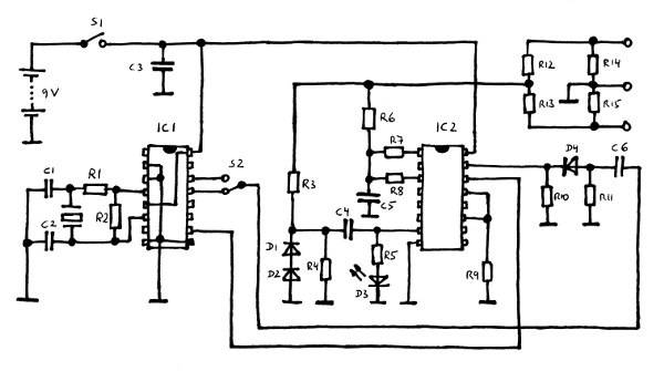 |
When one sequence is finished the shift register stops. Output 9 (pin11) is connected with EN-input (pin13). Only when a reset pulse reaches the counter (pin15) the counter starts again. This reset is also created by IC1. Because in addition to the 16 Hz trigger signal the IC also provides a 1 Hz and a 0.5 Hz signal at pin14 and pin13 which correlate a heart beat rate of 60 and 120 (switch 2). Therefore the square signal has to be transformed in a positive needle pulse. This is the duty of the combination C6, R11, D4, R10. Because this pulse comes earlier or later (0.5 Hz or 1 Hz) only the lengths of the U period is shorter or longer. The PQRST wave form is not effected.
A small LED D3 with resistor R5 connected to output 3 (pin7, IC2), flashes during the
R- period.
The final resistor combination R12-R15 converts the bipolar signal from the electronic board into the needed three pole output signal.
Note: The circuit is designed for common electronic devices. All parts can be found on old electronic boards or at the nearest electronic shop. But if you have problems to find the clock-crystal of 4.1943 MHz you can take a 4.43 MHz PAL-crystal from a TV. Your output signal is as good as with the clock-crystal but the heart rate will change to 63 and 127 beats per minute.
 |
 |
| (large image) |
(large image) |
Part list:
R1 = 4K7
R2, R8 = 1M
R3, R4, R9, R10, R11, R12, R13 = 100K
R5 = 1K
R6, R7 = 470K
R14, R15 = 220
C1 = 22 p
C2 = 82 p
C3, C4, C5, C6 = 220n
IC1 = 4521
IC2 = 4017
D1, D2, D4 = 1N4148
cristal = 4.1943 Mhz
D3 = LED 3 mm
2 x IC sockets 16 pin
Here the first design:
 |
 |
Here the second version:
 |
 |
| (large image) |
(large image) |
 |
|
| (large image) |
http://en.wikipedia.org/wiki/Electrocardiography
http://de.wikipedia.org/wiki/QRS-Komplex
4521
4017
 |
|