Capacitors
A capacitor is a passive electronic component which basically consist of two parallel metal layers separated by an insulator. The types of capacitors are named after this dielectric. We use capacitors with dielectrics made of ceramic, mica, polyester, tantalum etc.
Capacitors are used to block or to store voltages and to filter out signals.
Capacitors always have two pins. Some are bi-polar others mono-polar.
Mono-polar capacitors have two different leads, one positive and one negative.

|
Capacitors in different shapes and sizes. Mono-polar capacitors are usually cylindric while bipolar have disc or rectangular shape. |
Units, values and symbols
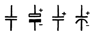
The formula letter of capacitors is C.The symbols for capacitors in circuit diagrams are shown below. Specially for electrolytic capacitors several different symbols exist.
|
Non-polar capacitor (left) and three mono-polar capacitors. |
The capacitor is characterized by the capacitance, which is measured in farad (F).
In practice the units are µF, nF, pF.
1,000 pF = 1 nF
1,000 nF = 1 µF
Non-polarized Capacitors
Capacitors of this type have no positive and negative terminal and can be mounted in both ways in the electronic board.Common non-polarized capacitors are made of ceramic, mica or polypropylene. Ceramic capacitors are small, cheap and are used for high frequency applications.
The main characteristic for anon-polarized capacitors is, that they block DC and let pass AC. They are also able to store voltages for a short moment.
Capacitors in electronics are mostly used in AC applications like signal filters and timing circuits.
Unlike the dielectric in polarized capacitors, the dielectric in non-polarized capacitors is a solid material that make the device durable and reliable. Failures of this type are rare.

|
Different non-polar capacitors. The small disks are ceramic capacitors. |
Beside capacitors with fixed capacity there also exist variable capacitors. But in hospital equipment they are not common.
Polarized Capacitors
Some capacitors such as electrolytic and tantalum are polarised. They have two different leads, plus (+) and minus (-). That means that they have to be connected in the correct way. The leads are always clearly marked.Polarized capacitors are mostly electrolytic capacitors. The construction is cylindric with connection lead on both ends (axial) for horizontal mounting or at one side only (radial) for standing mounting position.
For smaller voltages and capacities polarized capacitors made out of tantalum are often used. They are smaller and look different. They are drop-shaped.
Electrolytic capacitors offer very high capacity. The value of electrolytic capacitors is always µF.
Electrolytic capacitors are always marked with their maximum working voltage. The voltage across the terminals must never exceed this value.
In contrast to non-polarized capacitors the electrolyte is a liquid. In practice this fact is a source for a lot of problems.

|
The polarization is always mentioned. Often the negative (-) lead is marked. Capacitors are available for vertical and horizontal mounting. Vertical (or standing) mounting is also called radial. Horizontal (or laying) mounting is also called axial. |
Standard values
Similar to resistors the available capacitor values are standardized in the E-series. The most common series is E-12:10 12 15 18 22 27 33 39 47 56 68 82
Example: Available capacitors are 33 pF, 220 nF, 0.68 µF
Electrolytic capacitors have a higher tolerance. They are available only in E-6 or even E-3 graduation.
Example: 10 µF, 220 µF, 4.700 µF
Voltage
The second important characteristic of a capacitor is the proof voltage. This is the maximum voltage the capacitor can be used. This applies especially for electrolytic capacitors.Bipolar capacitors for electronic purposes (low voltages) often do not show the proof voltage because the voltages for electronic boards are much smaller than the proof voltages of the capacitors. Only for mains application (e.g. 230 V) the proof voltage has to be noticed.

|
Capacitor for mains. Here the proof voltage is very important (275 V AC) |
Tolerance
In addition to the capacity and the proof voltage the tolerance of the value is mentioned on the body of the capacitor. A single letter indicates the tolerance:J ±5% K ±10% M ±20%
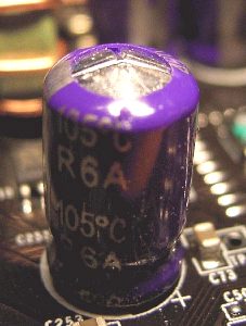
Example: A capacitor which has the following text on its body: 105 K 330 V
has the following specification:
1 µF (explanation next chapter), tolerance of ±10%, maximum voltage of 330 V.
Usually the tolerance of an electrolytic capacitors is higher than the tolerance of a non-polar capacitors. Tolerances of electrolytic capacitors are not important and so they are not mentioned on the capacitors. Tolerances of ±20% or more are common.
Capacitor Reading
If you are lucky, capacitance and maximum usage voltage are clearly marked on the capacitor.

|
µ47 means 0.47 µF or 470 nF J stands for 5 % tolerance 63 is the maximum usage voltage in V |
Often the reading of the values is not very clear. Too many numbers and letters can confuse you. Always look for numbers from the standard values.

|
Only the number 10n on top of the capacitor indicates the capacity: 10 nF K stands for 10 % tolerance and the 100 probably means the proof voltage. 1829 or 93 or 30 are not numbers of the standard values. They can mean everything but not the value. |
The reading of the value is often not easy because the units specially on bipolar capacitors are often missing. In principle then the value means µF.

|
The value 0.33 means 0.33 µF or 330 nF |
Only ceramic (disk) capacitors are different. Because their value is always very small, the value now means pF.

|
A ceramic capacitor without the unit. 27 in this case means 27 pF. |
To make it more confusing, sometimes the value is expressed as a 3 digit number code specially on ceramic capacitors. The first two digits are the base of the value and the third number indicates the multiplier or more simply, the number of zeros.

|
Another ceramic capacitor without the unit. Again the unit must be pF. 47 expresses a part of the value (E-series) and the 3 the number of zeros of the value. This capacitor has a value of 47,000 pF or 47 nF. |

|
683 K means 68 (3x 0) = 68 -000- pF or 68 nF with a tolerance of ±10% |
Example: 102 = 10 00 = 1,000 pF or 1 nF
224 = 22 0000 = 220,000 pF or 220 nF or 0.22 µF
471 = 47 0 = 470 pF
Exercise: What do the following characteristics of capacitors mean?
(To see the answer just
 the space behind the values)
104 K 50V 0.1µF, ±10%, 50V
473 M 100V 47nF, ±20%, 100V
68 K 50V 68pF, ±10%, 50V
For electrolytic capacitors it is more clearly. The value is always µF and this is also always mentioned.
The polarization is also always clearly indicated.

|
Capacity and voltage are printed clearly on electrolytic capacitors. 1000 µF 25 V (-) pin is down |
Combinations
Similar to resistors several capacitors can be connected in parallel or in series. But in contrast to resistors the capacity in series gets smaller and in parallel bigger.

|
Capacitors in series. The capacity gets smaller but the proof voltage gets bigger. 
|

|
Most common combination: Capacitors in parallel. The capacity can be simply added. The capacity gets bigger. The proof voltage remains the same. 
|
In practice the parallel combination is sometimes useful: The capacitor you need is not available but two of a smaller capacity. The capacities are simply added. The proof voltage of each capacitor must be as high (or higher) as the original.
Example: A 1000 µF/25V capacitor is needed but not available. But two capacitors of
470 µF/50V are available. In parallel the value will be 940 µF which is about 6%
less than the original. Because tolerances of ±20% are common this combination
can be used. This solution is even better than the original, because of the higher
proof voltage.
Applications
The two main characteristics of capacitors are storage of voltages and filtering.DC-Applications: Storage
Storage of voltage is a typical DC-application. DC voltage is stored for some time in a capacitor. The time of storage depends on the capacity and can be milliseconds or some seconds. Typical applications are power supplies where capacitors buffer the DC voltage to keep it stable and timer circuits where capacitors determine a switching time.

|
For voltage storage applications the capacitor is connected to ground (drawn always vertically). After switching off the DC voltage slowly falls off. |
The storage time depends on the capacity. The bigger the capacity the longer the time. For storage or buffering polarized electrolytic capacitors with high capacity are used.

|
After switching off the LED slowly gets dark. The bigger the capacity the slower the time. |
In power supplies high capacitive electrolytic are used to buffer and smooth the voltage. The capacitors clean the DC voltage from fluctuations and irregularities.

|
This is a part of the power supply of a pulse oximeter. The device in the centre is a voltage stabilizer IC. Input voltage and output voltage are filtered by the capacitors. |
AC Applications: Filtering
A decoupling capacitor is a capacitor used to separate one part of an electronic stage from another. That is important because different (analog) stages run by different DC voltages. The stages have to be separated DC- wise. DC has to be blocked but an AC signal has to pass. The capacitor filters out the AC-part of a signal.In schematics decoupling capacitors are usually drawn horizontal. The signal direction is from left to right (left = input, right = output).

|
A capacitor blocks the flow of DC. A DC voltage on one side as no DC effect on the other side of the capacitor. |

|
AC can pass through a capacitor. The loss (the AC resistance) depends on the capacity and the frequency of the AC-signal. |
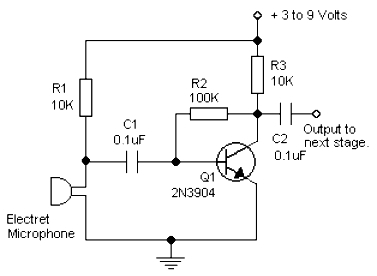
In electronics, AC-signals (sounds, heart beats, video images...) very often have to be amplified or converted. The electronic stages need power supply (DC) for operation. During the process AC signal and DC voltage are layered. Capacitors are needed to separate the stages DC-wise and to connect the stages AC-wise.
|
This is a small pre-amplifier. The microphone needs a certain DC voltage as well as the transistor. The DC voltages have to be decoupled but the microphone signal (AC) has to pass. C1 does this job. Also capacitor C2 leads the output signal to the next stage without any DC potential. The stages are AC-coupled and DC-isolated. |
Testing
A capacitance meter is an electronic test equipment used to measure capacitors. Upmarket digital multimeter often contain a function of measuring capacities. But in practice a capacitance measurement function is not really necessary because defectives on capacitors are usually visible.For measuring electrolytic capacitors keep in mind that they suffer from poor tolerances.
Tolerances of ±20% are common.
If you do not have a capacitance meter the function of electrolytic capacitors can be checked by connecting and disconnecting a voltage and measuring the stored voltage with a voltmeter. Depending on the capacity the voltage will drop more or less quickly.
With some multimeter you can switch on Ω range to charge the capacitor (by using the internal battery) and then switching over to the V range to see the voltage drop.
Troubleshooting
Most of the troubles with capacitors are coursed by electrolytic capacitors. Bipolar capacitors in electronic boards usually last for ever.The reasons for defective electrolytic capacitors are leakages, heat and poor production quality. Very often the cheapest quality is used with proof voltages very close to the operating voltage. After some time of working on the limit the capacitors become damaged. Electrolytic capacitors can leak, crack or even explode. In most of the cases the defect is visible. It is unusual that electrolytic capacitors loose capacity without any signs of damage.
This loss of capacity is often difficult to discover. The current does not get bigger, fuses are not triggered and nothing gets warm. The equipment seems to work somehow but not correctly. Voltages are not buffered, signals not filtered and other strange effects can appear.
Reasons for the defectives is the electrolyte inside the capacitor. Often the capacitor is not sealed perfectly and the capacitor leaks. The dielectric liquid also can vaporize under high temperature, can create a pressure on the capacitor case and makes the capacitor swell or even explode.
The leaked electrolyte can also corrode the printed circuit board where the capacitor is installed. Look for corrosion, clean the board and renew the solder points.

|
Defects of electrolytic capacitors are usually visible. Here the body is burst and the dielectric comes out. |
|
To prevent an explosion electrolytic capacitors have a perforation to let escape gases or the dielectric liquid in case of a failure. |
When changing a capacitor bear in mind the following:
 Make sure that the polarity is correct. Electrolytic capacitors store voltages for a long time.
Discharge electrolytic capacitors.
Make sure that the polarity is correct. Electrolytic capacitors store voltages for a long time.
Discharge electrolytic capacitors. by shorting the two terminal leads briefly. High voltage capacitors should be shorten by
a resistor (e.g. 1 KΩ). Check the voltage with your multimeter.
Choose capacitors with a proof voltage which is as high
or better higher than the original.Prices
Defects of non-polarized capacitors are rare. There is no need having them in stock. But some electrolytic capacitors should be available in every workshop.Here are the typical prices for capacitors in Europe:
| Ceramic | 0.10 € |
| MKS 630V | 0.20 € |
| SMD capacitor | 0.30 € |
| Tantalum 10 µF/25V | 0.30 € |
| Electrolytic 10 µF/40V | 0.20 € |
| Electrolytic 1,000 µF/40V | 0.80 € |
| Electrolytic 4,700 µF/63V | 4.00 € |
Sources and additional information
Capacitors: http://en.wikipedia.org/wiki/CapacitorsTypes: http://en.wikipedia.org/wiki/Types_of_capacitor
Electrolytic Capacitors: http://en.wikipedia.org/wiki/Electrolytic_capacitor
Applications: http://en.wikipedia.org/wiki/Applications_of_capacitors
Defects: http://en.wikipedia.org/wiki/Capacitor_plague
 |
|