Electrical Safety Testing |
by Frank Weithöner |
Manufacturers of medical equipment ensure that all safety regulations during the design and manufacture are complied with and a safe equipment has been produced. Now it is the task of the hospital (hospital workshop) to ensure that the equipment remains safe during usage. In the developed world electrical safety tests are compulsory after every repair of a medical equipment and are furthermore, part of the preventive maintenance procedure (PPM).
National and international organisations like ANSI, BSI, EEC, IEC, ISO, NETA, NFPA have defined safety standards and test procedures. For medical equipment IEC 62353 is the most widely applied testing standard.
Situation in developing countries
In developing countries the above mentioned safety standards are hardly applied. There are different reasons for this: Monitoring organisations do not exist, the hospital management is not aware of the importance of safety tests, the technical department has no time or money to implement safety tests, and the technicians do not know how to perform the tests or they point out that the needed special measurement equipment is not available.This does not have to be the situation: Electrical safety tests are not difficult to perform and special test equipment is not really needed. (↓Test equipment)
 But, it is also important to understand that the challenges in developing countries are different. For example: Why should a technicians perform safety tests
on medical equipment while the electrical installation in the hospital is faulty, fuses and RCDs are missing, wall sockets are broken and power plugs
are missing do not make the hospital safer? Electrical safety tests in developing countries should therefore, (and particularly) cover checking the
environment of the equipment and not only the equipment itself.
But, it is also important to understand that the challenges in developing countries are different. For example: Why should a technicians perform safety tests
on medical equipment while the electrical installation in the hospital is faulty, fuses and RCDs are missing, wall sockets are broken and power plugs
are missing do not make the hospital safer? Electrical safety tests in developing countries should therefore, (and particularly) cover checking the
environment of the equipment and not only the equipment itself.Visual inspection
Every safety test should start with a visual check of the equipment and its power supply. Especially in low-income countries this is the most important part of an electrical safety test because most of the dangerous damages are visible and do not need complex measurements.A simple visual inspection from the outside of the equipment should cover:
 The wall socket.
Is the wall socket in good working order or is it damaged?
The power plug.Is the power plug OK and of the correct system?
Are the contacts clean or are they charred?
The power cable.Is the power cable damaged? Brittle and patched power cables have to be replaced.
The strain relief.Pull the cable. Is the strain relief tight? Check on both sides, on the equipment and on
the plug. (How to connect a mains plug)
A simple visual inspection of the inside of the equipment:
Does the equipment show signs of overheating and burns? Are all cable connections tight? Look out for loose cables. Are there any bare wires? Are the fuses correct? Bypassed fuses have to be removed immediately. Test equipment
Since safety tests for medical equipment are often time-consuming all hospital workshops in the developed world have automated electrical safety tester (safety analyser). These tester are multiple function tester and they carry out all tests automatically, no settings and connections have to be changed. The test results are printed out afterwards. The technician does not even have to know how the tests are performed or what the value limits are. This is very handy and time-saving. But these analyser are also expensive and thus almost non-existent in hospital workshops in developing countries.But the different tests can still be carried out manually - even without special measurement equipment. We only have to know what tests should be done, how they are carried out and how high the limit values are allowed to be. And for measuring we only need a common digital multimeter.
Test procedures
In the following the different equipment classes and types are explained. This is important because test procedures and test results depend on the this identification. Then the different electrical safety tests and test methods are described. Here also the limit values are given. After performing a test the measured value has to be compared with the limit value. Is an equipment within the limit value it has passed the test. The test result should be written down in a test report or job card. Then the next test can be carried out.The introduced test procedures are particularly suitable for hospital workshops in low-income countries. The tests are easy to carry out, provide reliable results and no expensive safety analyser is needed.
Please note, that the suggested test procedures do not cover every safety aspect. One or the other test might be missing. But nevertheless, any test, even the simplest is better than no test.
Appliance classes and types
All electrical equipment are divided in different appliance classes depending on the method of protection against electric shock. The protection can consist of the usage of a protective earth, a double insulation or a separate power supply.Before an equipment can be tested for its safety the appliance class has to be determined. In order to simplify the identification each class has its own symbol which should be found on the rating plate of the equipment.
For medical equipment this classification is not sufficient enough because a medical equipment of the same class can be made for the usage without a connection to a patient, with a connection to the patient's skin or for a connection to the opened body of a patient. These different degrees are expressed by the appliance type.
Class I
A Class I equipment has a protective earth connection (PE). This earth connection is connected to all exposed metal parts, especially to the metal housing. The connected power cable is thus a three core mains cable and the power plug has three pins.
 The user is protected by a basic insulation and the protective earth connection. In the event of a fault when line comes in contact with the metal
enclosure the fault current is shortened to ground, a big short-circuit current flows and the fuse inside the equipment blows or the circuit breaker
(MCB) in the distribution board gets tripped.
The user is protected by a basic insulation and the protective earth connection. In the event of a fault when line comes in contact with the metal
enclosure the fault current is shortened to ground, a big short-circuit current flows and the fuse inside the equipment blows or the circuit breaker
(MCB) in the distribution board gets tripped.Medical equipment should be additionally protected by two internal fuses, one for the line path and one for neutral. In many countries L and N are not defined and the power plug can be inserted into the wall socket in both ways. Then the neutral fuse which is theoretically useless becomes the important line fuse. Also, smaller fuses inside the equipment blow faster than a MCB which is made for higher currents.
 The symbol for Class I equipment is the earth sign in a circle which should be imaged on the rating plate. But the use of this symbol is not mandatory.
Many equipment have no symbol. Then it can be considered as Class I.
The symbol for Class I equipment is the earth sign in a circle which should be imaged on the rating plate. But the use of this symbol is not mandatory.
Many equipment have no symbol. Then it can be considered as Class I.Class II
A Class II equipment is double insulated and not earthed. Safety is achieved by two (or more) layers of insulating material between live parts and the user. Earthing is not necessary.
In case of a damage of one insulation the second prevents any external parts from becoming alive.
The Class II equipment is usually connected with a 2-pin plug/cable to mains. But also 3-pin connections can be used. In this case PE must not connected to the metal housing of the equipment. Class II equipment usually have only one internal fuse.

The symbol for Class II equipment is the double box which should be imaged on the rating plate.
Class III
A Class III equipment is a low-voltage equipment. The voltage is so low (Safety Extra Low Voltage, SELV) that a person who gets in contact with it does not get an electric shock.
The equipment runs either on battery or on an external power supply which creates a supply voltage of less than 50 VAC. The testing of Class III equipment is done in conjunction with the power supply tested in Class I or Class II.

The symbol for Class II equipment is the Roman III inside a rhombus which should be imaged on the rating plate.
Isolation transformer
The use of an isolation transformer is not specified in an extra safety class but it is a another possibility of protection. The isolation transformer is a 1:1 transformer which provides a galvanic isolation from line potential to earth. The output voltage is only present between the two output connectors and no longer from one (line) to ground. The output socket has no PE connection and may only be used for one equipment.
The isolation transformer is used for special equipment in the operating room and in the workshop. Especially in the workshop the isolation transformer should be always used when working on energised equipment (e.g. switched mode power supplies).

The symbol for a transformer is also find on external power supplies when they contain a transformer.
Types
The equipment classes define the method of protection against electric shock. For household appliances this is good enough but not for medical equipment. A medical equipment of one class can be used without a connection to a human body (e.g. suction pump), with a patient connection (e.g. pulse oximeter)
and inside the body of a patient (e.g. electrosurgery unit). That is why the appliance classes are again divided in different types. The types define
the degree of protection.
A medical equipment of one class can be used without a connection to a human body (e.g. suction pump), with a patient connection (e.g. pulse oximeter)
and inside the body of a patient (e.g. electrosurgery unit). That is why the appliance classes are again divided in different types. The types define
the degree of protection. For this reason we find two symbols on the rating plates of medical equipment, one for the method of protection (class) and one for the degree of protection (type).
Type B
In combination with medical equipment of Class I, II, III.
 Standard degree of protection against electric shock. No electrical contact with a patient. Equipment may be connected to earth. Patient connections
are not conductive and can be immediately released from the patient. Standard values for permitted leakage currents are demanded which are stated
under the respective test procedure.
Standard degree of protection against electric shock. No electrical contact with a patient. Equipment may be connected to earth. Patient connections
are not conductive and can be immediately released from the patient. Standard values for permitted leakage currents are demanded which are stated
under the respective test procedure. Type BF
In combination with medical equipment of Class I, II, III.
 Equipment is safe for electrical connection to the patient but not directly to the heart. The patient part of the equipment is isolated (floating
circuit) and has to be separated from earth. Standard values for permitted leakage currents are demanded which are stated under the respective test
procedure.
Equipment is safe for electrical connection to the patient but not directly to the heart. The patient part of the equipment is isolated (floating
circuit) and has to be separated from earth. Standard values for permitted leakage currents are demanded which are stated under the respective test
procedure.  When the equipment can be used in combination with a defibrillator this symbol has to be printed on the rating plate. It means defibrillation-proof.
Type CF
In combination with medical equipment of Class I, II, III.
 Equipment provides highest degree of protection against electric shock. It is safe for electrical connection to the heart of the patient. The patient part of the equipment is also isolated (floating circuit) and is separated from earth like BF.
The permitted leakage current is much lower than for type B and BF. The values are stated under the respective test procedure.
Equipment provides highest degree of protection against electric shock. It is safe for electrical connection to the heart of the patient. The patient part of the equipment is also isolated (floating circuit) and is separated from earth like BF.
The permitted leakage current is much lower than for type B and BF. The values are stated under the respective test procedure.  When the equipment can be used in combination with a defibrillator this symbol has to be printed on the rating plate. It means defibrillation-proof.
Electrical safety test procedures
The following tests are electrical safety tests for medical equipment. Tests on the electrical installation especially earthing are not considered. These tests need further knowledge, special test equipment and should be carried out by experienced electricians only.After testing all test results should be documented on a test report. Tested equipment should get a sticker which shows the user that the equipment is safe and the date of the next test.
An equipment with a results beyond the value limit must not be used again until the fault has been rectified.
These electrical safety tests are described in the following:
Protective earth continuity test (1.) Insulation resistance test (2.a) Earth leakage current test (3.a) Touch current / Enclosure leakage current test (3.b) Patient leakage current test (3.c)1. Protective earth continuity test (Class I)
With this test the resistance of the PE conductor is measured between the PE connection of the mains plug and the unpainted metal housing of the equipment. This is the most important test and we should always start safety tests with this one. If an equipment fails this test it will also fail the other tests.According to many guidelines this test should be done with a safety analyser or PAT tester. The analyser applies a 50 Hz AC-current to the PE connection. For testing electrical equipment (e.g. motors) a test current of 10 A or even 20 A for at least 5 seconds is demanded. Since this current can be much too high for many electronic and medical equipment other standards suggest a test current of 1 A or even only 200 mA.
For this reason there is nothing wrong testing the protective earth continuity of medical equipment with an ohmmeter. The measurement conditions are not perfect but on the other hand the ohmmeter does not do any damage to the medical equipment.
 Equipment is disconnected from mains. Continuity tester is connected to the metal housing of the equipment and to PE of the
 mains plug.
Equipment is switched on.The resistance should be ≤ 0.2 Ω
| For low-income countries: When a safety tester is not present, an ohmmeter with good resolution can be used instead. |
2a. Insulation resistance test (Class I)
With this test the insulation is measured. Therefore an insulation or safety tester (e.g. Megger) is needed. The tester delivers a high DC voltage to the equipment under test and then the resistance of the insulation in between is measured.Standard test voltage for electrical equipment is 500 V. Electronic and medical equipment which often contain voltage limiting devices such as MOV or EMI-filters should be tested at 250 V.
The tester is connected between the mains plug with L and N connected together and PE.
 Equipment is disconnected from mains. Equipment is switched on. Insulation tester is connected between L+N and PE.
The resistance should be ≥ 2 MΩ (medical equipment)
≥ 1 MΩ (on electric motor), ≥ 0.3 MΩ (on equipment with heating element)
| For low-income countries: Instead the insulation test a patient leakage current test can be done (3a). |
2b. Insulation resistance test (Class II)
The insulation resistance test for Class II equipment is different because the mains plug has no PE connection. The insulation resistance is measured between the patient cables which are all connected together and exposed and unpainted metal pieces (e.g. screws, sockets) of the equipment.Standard test voltage for electrical equipment is 500 V. Electronic and medical equipment which often contain voltage limiting devices such as MOV or EMI suppression should be tested at 250 V.
 Equipment is disconnected from mains. Equipment is switched off. Insulation tester is connected between all patient cables and exposed metal pieces.
The resistance should be ≥ 2 MΩ
| For low-income countries: Instead the insulation test a patient leakage current test can be done (3c). |
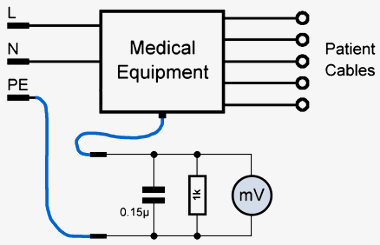
3. Leakage current test device
The leakage current through a human body can be simulated and determined by inserting a known impedance into the ground connection and then measuring the voltage drop across it. The recommended measuring device consists of a 1 kΩ resistor and a capacitor of 0.15 µF in parallel. The voltmeter has to have at least 1 MΩ impedance, so it has to be a digital one.Leakage current tests with such a test device are standard test procedures for medical equipment and are recommended by almost all medical equipment manufacturers.
The displayed measurement result in mV is equal to a current in µA (1 mV ≙ 1 µA).

The following three different leakage current measurements should be made, each under two conditions: Normal condition (NC) and single fault condition (SFC), when the earth or neutral connection is interrupted.
Earth leakage current Touch current (enclosure leakage current) Patient leakage current3a. Earth leakage current test (Class I)
This test simulates and measures a leakage current through the ground wire to earth. The test is done in normal operation mode and in single fault condition (open neutral).The measurement of the leakage current can be used as a substitute for the insulation resistance test (2a). In fact it is even better do this test instead because the high voltage of the insulation test may cause damages to the equipment on test when MOVs and Y-capacitors of EMI-filters are present.
The equipment under test has to be switched on. The measurement should be done with normal mains polarity and in reverse.

Normal condition
Equipment is switched on. Normal polarity Reverse polarityLeakage current should be ≤ 0.5 mA (B, BF, CF)
Single fault condition - Open neutral, N
Equipment is switched on. Normal polarity. Reverse polarity.Leakage current should be ≤ 1 mA (B, BF, CF)
3b. Touch current / Enclosure leakage current (Class I and Class II)
This test simulates and measures a leakage current through the exposed conductive surface to earth. The test is done in normal operation mode and in single fault condition (open neutral, open PE).The equipment under test has to be switched on. The measurement should be done with normal mains polarity and in reverse.
Normal condition
Equipment is switched on. Normal polarity. Reverse polarity.Leakage current should be ≤ 0.1 mA (B, BF, CF)
Single fault condition - Open protective earth, PE (Class I only)
Equipment is switched on. Normal polarity. Reverse polarity.Leakage current should be ≤ 0.5 mA (B, BF, CF)
Single fault condition - Open neutral, N
Equipment is switched on. Normal polarity. Reverse polarity.Leakage current should be ≤ 0.5 mA (B, BF, CF)
3c. Patient leakage current (Class I and Class II)
This test simulates and measures a leakage current through the patient connections to earth. The test is done in normal operation mode and in single fault condition (open neutral, open PE).The equipment under test has to be switched on. The measurement should be done with normal mains polarity and reverse.
The patient leads of B and BF equipment are connected together and are then measured against earth. In case of an equipment of CF type the currents should be measured separately, through each patient connection to earth.
The equipment under test has to be switched on. The measurement should be done with normal mains polarity and in reverse.

Normal condition
Equipment is switched on. Normal polarity. Reverse polarity.Leakage current should be ≤ 0.1 mA (B, BF) ≤ 0.01 mA (CF)
Single fault condition - Open protective earth (Class I only)
Equipment is switched on. Normal polarity. Reverse polarity.Leakage current should be ≤ 0.5 mA (B, BF) ≤ 0.05 mA (CF)
Single fault condition - Open neutral
Equipment is switched on. Normal polarity. Reverse polarity.Leakage current should be ≤ 0.5 mA (B, BF) ≤ 0.05 mA (CF)
What else can be done?
The hospital personnel should be encouraged to report any (safety) problem, damage or unusual effect to the technical department. This also applies to damaged plugs and wall sockets as well as equipment with mains plugs of the wrong type.Inform the personnel about the right plug system and the importance of using adapters. Offer adapters or better change wrong power plugs.
But this also means that a sufficient number of spare wall sockets and mains plugs have to be in stock and available at any time. It does not make sense to explain the importance of electrical safety when the repairs can not be carried out immediately.
Most of the wall sockets in hospitals in developing countries today are occupied by mobile phone chargers of the hospital staff. This is particularly bad when therefore hospital equipment is disconnected. Even when some equipment are not in use at the moment they might need mains in order to charge internal batteries. Discuss with the hospital management a ban for mobile phone chargers in hospital departments. But on the other hand also provide charging possibilities (distribution sockets) in e.g. nurses' rooms.
Take a sufficient amount of spare mains plugs and wall sockets in stock. Encourage hospital personnel to report any damage of plugs, wall sockets and powercords.
Perform regular tests of all RCDs in the hospital (e.g. once a year). Perform regular tests of all medical equipment (as part of preventive maintenanceprocedure).
Conduct safety tests after every repair.Links and sources
Wikipedia: Appliance classesWikipedia: Electrical safety testing
Wikipedia: Electric shock
Wikipedia: Portable appliance testing
 |
|